Measuring Interrupted Features
Measuring Interrupted Features
In CMM based metrology we often encounter interrupted features, or features made up of multiple surfaces considered as one entity.
For example, a door hinge might have 3 separate coaxial cylinders considered as one datum feature. Another example could be a bracket with multiple coplanar mounting surfaces that interface with a single unit. These multiple surfaces may be considered as a single interrupted feature instead of individually controlled planes. CAD Teach Feature are only associated with a single CAD surface entity, so evaluating these interrupted features creates room for some different approaches.
Lets use this interrupted circular plane as an example:
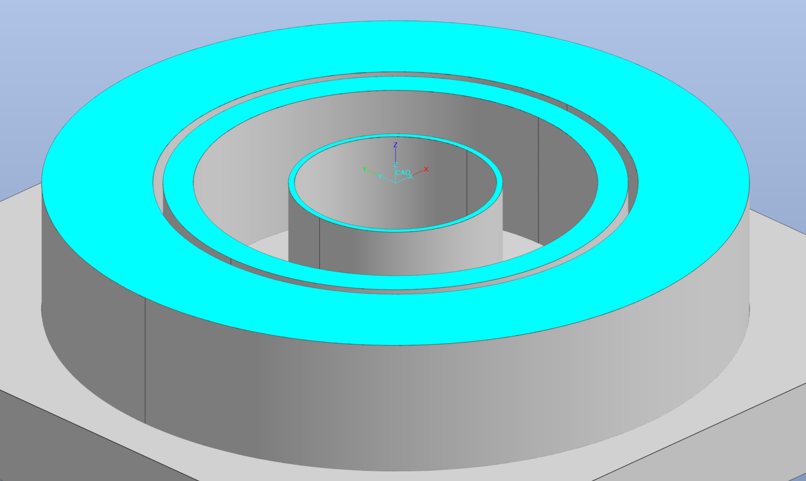
This components Datum -A- is an interrupted feature made of 3 coplanar circular planes. These 3 separate CAD entities need to be considered as one for purposes of establishing a reference frame for measurement.
We have several ways we can go about this, with each method having its own advantages to better suit different applications.
Cloud-to-Feature method
When teaching an interrupted feature from CAD a user may find the path of least resistance is to create multiple measured features, then extract the raw data and best fit everything back into a single unified feature. This certainly works, but takes multiple steps and/or program lines to measure something that needs to be considered as one entity. We can save a program line and some mouse clicks for every surface by creating CAD Teach Clouds directly instead of extracting raw data from fitted features.
To start, we measure the surfaces as CAD Teach (Full Auto) Clouds ensuring that probe compensation is turned Off. This example is conducive to using the Along Edge path options instead of a target grid:
When measuring multiple of the same feature we can click the Pin button at the top of the window to keep this tool active. This allows us to keep selecting CAD surfaces without re-clicking the Cloud button:
We want to create a cloud on each surface of the interrupted feature:
Then we create a Best Fit feature from the clouds, ensuring we check the Apply box to enable Probe Compensation at the fit level:
We should observe the red arrow to confirm our outward normal orientation for the best-fit feature:
In the case of this plane, we have some Advanced Options for fitting and filtering to help simulate how Datum -A- may interact with a surface:
Once we are happy with our configuration we can hit OK to teach the Best-Fit construction to the program database:
This method results in a Datum -A- feature with all of the surfaces considered as one, along with our single-surface clouds that can still be evaluated individually or as a group for things like direct Cloud deviation or Cloud-to-CAD report items. When using the Full Auto Path Planning option, the above mentioned method is likely the fastest way to capture this measurement and still allows us to easily report items from the individual surfaces.
Points Added method
We can also take a different approach in an effort to keep the measurement for the interrupted surface to one program line. Instead of teaching 3 individual CAD measurements, we can teach one CAD feature containing the points for all of the surfaces.
CMM-Manager will auto path to a selected CAD entity, so to minimize our work we will select the largest surface of the interrupted feature:
Once we are happy with our point configuration for the largest surface, we can go to the points tab and add our extra points. We will look at two options for adding points, the first is the Add Pick button under Graphics Tools:
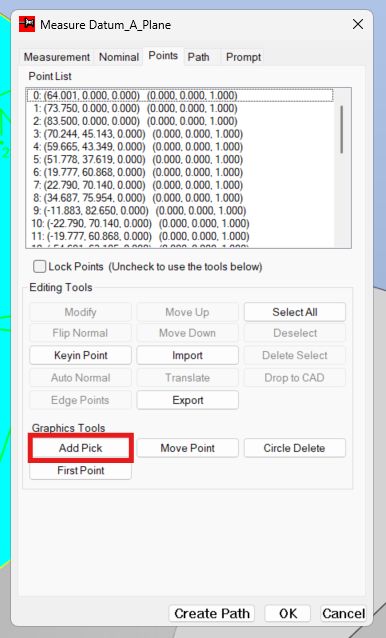
This allows you to directly click the desired points on the graphic:
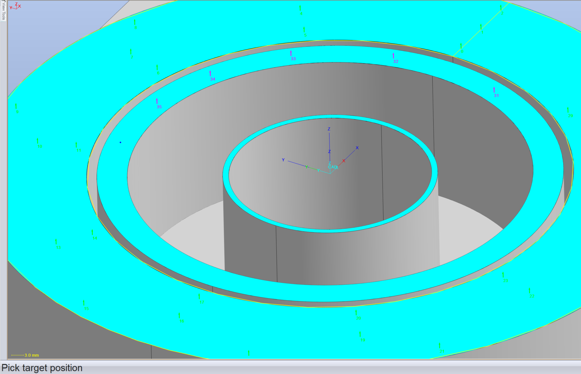
*click ESC once all of your points are selected from the graphics*
Your other option is to key in points directly using the button under Editing Tools:
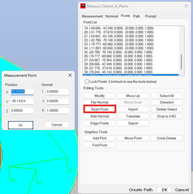
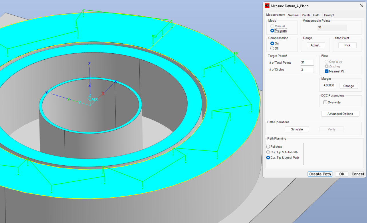
Once we are happy with our point placement we can click Create Path to automatically generate a collision free measurement path that incorporates the added points:
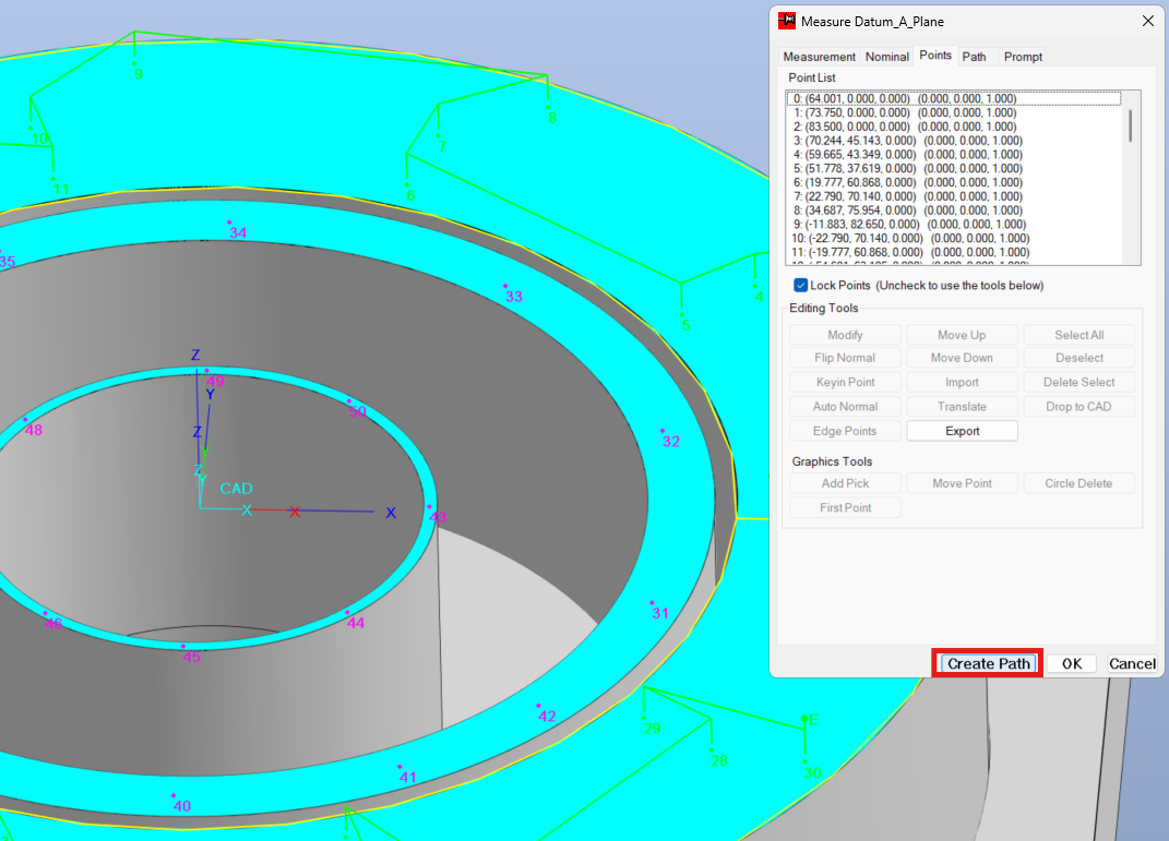
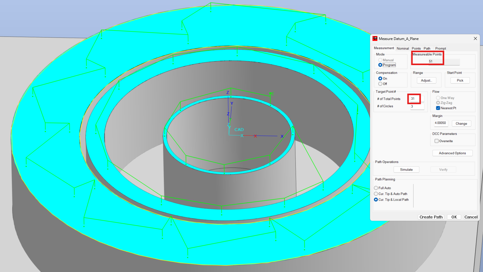
We now have a safe path to measure our interrupted feature as a single plane, confirmed by the difference in Target Points and Measurable Points:
Like our previously discussed Best-Fit feature, we can apply a Fitting Algorithm to our interrupted feature through Advanced Options:
Once we are happy we can hit OK to teach the feature to the program database:
This method results in a single program line for our Datum -A- feature. This method could potentially decrease load times when opening a project/program and decrease processing times from the system side. Fewer items in the Program Database also makes for a more streamlined program review in environments where multiple people are handling and managing the program files.
Transform-for-Fit method
There is another option for creating points that takes advantage of the transform function. It takes a few steps but can be useful for creating a more efficient path with certain features. It is also comes in handy when a CAD model is not available.
We need to create a base feature group for transformation, so we will start by teaching points (or a cloud) ensuring probe comp is off. In this case I am taking 15 individual points along the Y-axis:
Once we teach our base feature group, we can highlight/select the features in the program database, right click and select transform:
We have several options to configure this transformation. For details on the Transform Operations command, check out our knowledge base article on Transform Operations.
For this example we are rotating 10° about the active reference Z axis, 35 times, with the intent to fully cover this interrupted surface:
Once we are happy with our configuration we can click OK to perform the Transform Operation, observing the manipulation and/or new items populate in our Program Database and Display Window:
We now have a collection of points that can be Best-Fit to our final plane feature. When configuring your Best-Fit Construction, verify that your Outward Normal direction is correct and ensure Probe Compensation Apply is checked to properly fit the feature:
This is our opportunity to apply a fitting algorithm or filter scanned points through Advanced Options:
Once we are happy with the configuration we can click OK to teach the Best-Fit Construct feature to the program database:
Using this method can result in more lines in the program database but can take significantly less clicks, especially for high point density features. In some cases it can even result in a more efficient measurement path.
While we use the CAD Teach Points in this example, the same approach could be applied with DCC Define and other Teach methods when CAD is not available.
Final Thoughts:
With several possible approaches, there is no true best option. The best one for your application will be dependent on the balance of factors such as time to write, time to execute, time to manipulate. Some methods prioritize minimal input and others minimal execution time and system load. Some are more useful with CAD, while others become very helpful when CAD is not available. That said, all of the discussed approaches should apply to most other interrupted features such as cylinders, cones, spheres, etc.
If you have any questions regarding your specific interrupted feature measurement, you can create a post in the CMM-Manager Community or send your question to support@qxcmm.com.
Related Articles
Next Steps - Import CAD, Alignment, Measure Features
Here’s a short video showing the typical workflow for getting started in CMM-Manager when you want to import CAD, align the part, and measure using 3D CAD. <br><br> 0:00 Introduction 1:18 3-2-1 ...Picking Features for Alignment, Constructions, and Reporting
There are several methods available for selecting individual or multiple items within CMM-Manger: 0:00 Mouse Picking (from CAD) 0:21 Drag-n-Drop (from Feature Database) 0:52 Right Click (Drop down menu)SmartSCS for FDA 21 CFR Part 11
Introduction Smart SCS is a simple user interface for a wide variety of measuring instruments and technologies: optical measuring machines, CMMs, CT systems, laser scanners and fringe projection systems, as well as contour, roughness and wave ...NIST Algorithm Test / PTB Certificate
3rd party PTB certification that tests fitting Algorithm of (typically) metrology software has been complete on CMM-Manager. The PTB certificate for CMM-Manager is attached below. This 3rd party certification and NIST tracible validation should ...GD&T - Composite Position
This Knowledge Base article describes how to configure and report Composite Position using CMM-Manager. For a detailed description of the Composite Position tolerance and how it is properly applied, refer to the appropriate topic in the current ASME ...