The Renishaw ACR1 tool change rack is used with Renishaw probing systems, which utilize the AutoJoint style tool connection system. The ACR1 rack requires additional components and wiring to the controller to control the locking and unlocking of the tools during a tool change.
Installing the ACR1 Rack
The ACR1 rack can be mounted in any convenient location along the sides or back of the machine. The ACR1 rack requires extra control equipment and wiring. Please contact your Authorized Renishaw integrator for assistance.
Configuring the ACR1 Rack
Note: If you are using an ACR1 rack with a system using the I++ protocol, the configuration is done in the I++ Server software.
The following steps are required to configure the ACR1 rack for use.
Making the ACR1 available to CMM-Manager
The first step is to let CMM-Manager know that a rack has been installed. This is done from System > Setup > Machine Setup on the Ribbon bar.
Select the Probe tab from the Machine Setup dialog, select the type of rack you have installed, and click ADD to add the rack to the available racks list. More than one rack may be installed at one time. Depending on the probing system, the racks may be mixed and matched.
Once you have added any racks to the Machine Setup, click Apply to save the changes, then click OK to close the dialog.
Assigning Modules to a Port (ACR1)
Next, we need to assign the port to use to store the various tip modules. Not all ports must be filled, and not all tip modules must be assigned a port.
Note: If a tool is not assigned to a port, and that tool is requested during a program, the user will be prompted to place that tool on the probe manually.
After creating definitions for all of the available tools using the Probe Assembly dialog, select each tool, in turn, click assign, then select the probe station and the port that will be used to store that tool. Click OK on the Assign Station and Port dialog, then continue through the rest of the tools in the same manner.
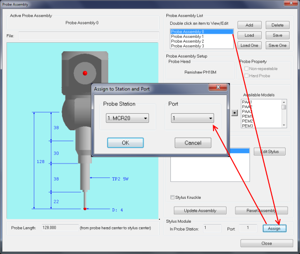
Tools will be loaded into the correct ports later.
Teaching the ACR1 Rack Location
With the ACR1 rack, you can perform both full and partial calibrations to compensate for homing repeatability issues. Once you have completed a full calibration, you may calibrate the rack from then on with a partial calibration that only requires measuring the datum stylus to determine the rack's location.
Before attempting this procedure, you must have added an ACR1 rack in Machine Setup.
| |
| Select Probe Tab Rack Group Calibrate in the Ribbon Bar (or click the Calibrate Station button in the Probe Station dialog)
 The Calibrate Station dialog pops up: 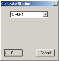
If the probe station has been previously calibrated, the dialog appears with the option to calibrate partially: 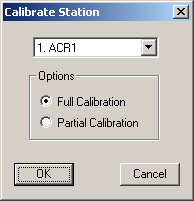
Select a full or partial calibration in the Options box.  NOTE: If you select a partial calibration, proceed to Step 6. |
| Select the ACR1 probe station to calibrate from the dropdown list and click OK.
The Before Calibration dialog pops up. 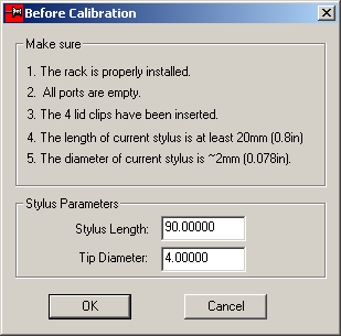
|
| Follow the procedures listed in Things to Do to prepare for calibration.
The Stylus Parameters are automatically retrieved from the active Probe Assembly and may be overridden by typing the values in the input boxes:
- Stylus Length - the length of the stylus module, from the mounting surface to the stylus ball center.
- Tip Diameter - the diameter of the stylus tip.
|
|
| Click the OK button.
The Move to the entry... message box appears. 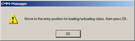
|
| Move the probe to the desired entry position, where the path for changing the probe is clear, and click the OK button.
A measurement counter, illustrating an ACR1 Probe Station, appears. 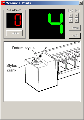
|
| Measure points P1, P2, P3, and P4 on the datum stylus of the rack. NOTE: For a partial calibration, the calibration is finished, and a message appears: For a full calibration, a measurement counter for top plane points P5, P6, and P7 appears: 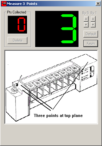
|
| Measure points P5, P6, and P7 on the top plane of the rack.
A measurement counter for front plane points P8, and P9 appears: 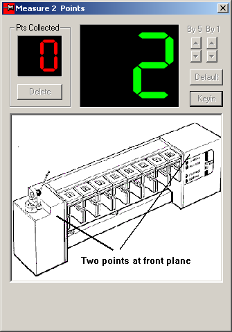
|
| Measure points P8 and P9 on the front plane of the rack.
A measurement counter for side plane point P10 appears: 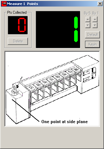
|
| Measure point P10 on the side plane of the rack.
CMM-Manager begins DCC calibration. 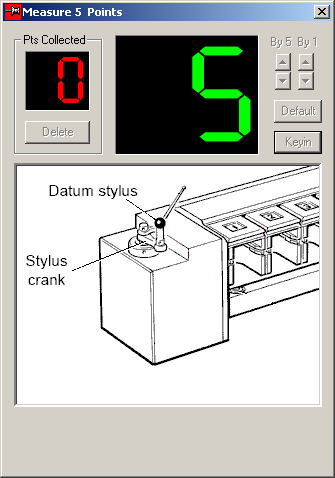
|
| The calibration is completed; the probe station status changes to calibrated.
|
Loading Components into the ACR1 Rack
It is recommended that modules and tips are initially loaded into the rack by the machine. If the user manually places the component into the rack, it may not be in the correct position or pickup orientation. If the machine places the component, it will be correctly positioned for pick up when next used.
Before the rack is loaded with tools, it must first be configured properly, and it's location taught.
Once the proper setup is complete, we can begin loading the rack.
From the Ribbon Bar, select Probe > Rack > Configure. The following dialog will be displayed.
Select the Probe Station (rack) to be used. The Station speeds will usually have reasonable default values for the tool docking process.
In the table, highlight the Port # to be used to store a tool.
Note: The values which are pre-configured in this table were set in the topic Assigning components to a port
Click [STORE]. The user will be prompted to attach the component to the tool manually. After clicking OK, the machine will move to the rack and store the tool in the proper port.
Continue through the list storing the tools in their proper locations. Be sure to do this for all racks when multiple racks are used.
Once this process is complete, you may click Apply Changes and then Close this dialog.
Using the machine, from the Ribbon Bar, select Probe > Probe group > Get Probe Assembly. Select the desired probe from the drop-down list and click OK. The machine will then go and automatically load the proper tool.
Any other Get Probe Assembly commands used in a program will cause the machine to do a tool change automatically.
WARNING: When writing a program, be sure there is a clear path to the probe rack when selecting a new tool. It may be necessary for the programmer to add their own clearance moves to ensure a collision-free tool change.


